
Source: Kyotoku Data download:KTCD-AN007
As power supply output current requirements continue to increase, it is important for the design engineer to pay close attention to inductor power losses and their affect on overall power supply efficiency.
The demand for an improvement in power supply efficiency, and therefore, inductor efficiency has increased quite rapidly. This demand has come as a result of an increase in power supply output current. At the same time, there has been a renewed effort to reduce the amount of heat that power supplies have to dissipate, which has a direct effect on overall power supply efficiency. The reduction in heat creation is especially important to laptop users.
Since heat creation and inductor power loss are directly related, it is extremely important to reduce inductor power losses. To reduce these losses, it is necessary to understand where the they come from.
There are several main inherent losses associated with inductors, they are:
Copper Wire DC Loss
Copper Wire AC Loss (Skin Effect, Proximity Effect )
Core Hysteresis Loss
Core Eddy Current Loss
Each of these losses and the primary causes of them are listed below, the results of these losses are to lower efficiency and to produce heat, which further increases the losses in the inductor.
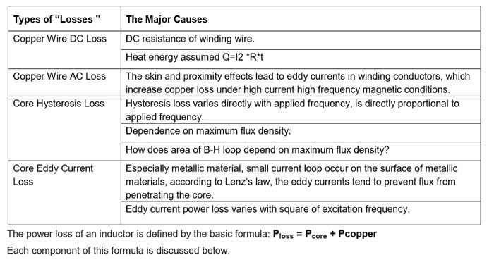
1.Core Loss(Pcore)
Core loss includes Core Hysteresis Loss and Core Eddy Current Loss,that is,
Pcore= Core Hysteresis Loss+Core Eddy Current Loss, Core Loss can be calculated by the formula: Pcore=Pcv*Ve
(1) Pcv is core loss consumed in unit volume, which can directly be got from the master data curve of core raw material in core supplier's catalogue, Pcv varies with Flux Density and Frequency.(Example:TDK Core PC47).
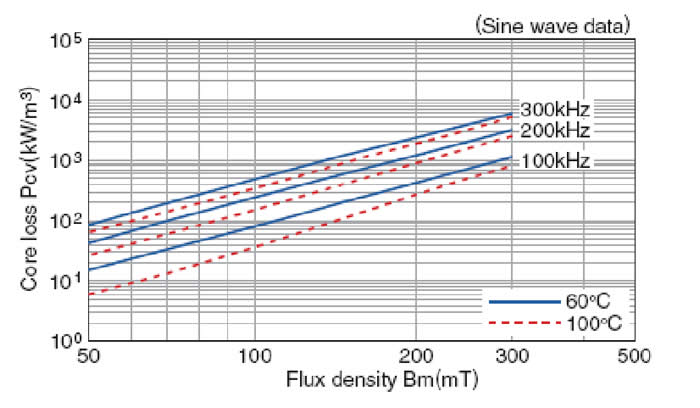
Before you use the above curve to look up Pcv , you must calculate Flux Density B first from the Formula as follows:
Flux Density: B=[L*I /Ae]*Np Where: B: Maximum magnetic flux density in hysteresis loop B(T) L :Inductance(μH) I : Current(A),rated current is often used. Ae:Effective cross-sectional area(mm2),can be got from core specification or core catalogue. Np:Winding turns (2) Ve is effective volume which can be got form the core specification(based on No Gap core). Ve=Ae*Le Where: Ae: effective cross-sectional area, Le: effective magnetic length. In International Standard IEC60205 “Calculation of effective parameters of magnetic piece part”, Uniform rules for the calculation of effective parameters of ferromagnetic material is provided for some core types(No drum core,drum core+ring core are included).
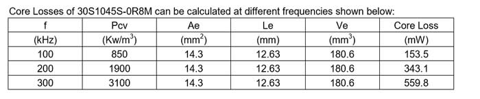
An example is given to describe how to calculate Pcore for Magcoils Part Number : 30S1045S-0R8M:
·Ls=0.8μH, I=15.5A (supposed) , Np=3T ·Ae of Core PC44 (supplier:TDK): =14.3mm2 from TDK’s catalogue.
The Flux Density B can be calculated from the following formula:
B= [L*I /Ae]*Np = [0.8*15.5/14.3]*3 =0.261T=261mT
From TDK PC47 Flux Density B(mT) curve,Pcv is about 850 kW/m3 at B-261mT and F=100kHz, From Core material specification:Ve=Le*Ae=14.3*12.63=180.6 mm3
Pcore=Pcv*Ve=850 kW/m3*180.6 mm3=153.5mW
Core Losses of 30S1045S-0R8M can be calculated at different frequencies shown below:
There is another way to calculate the core loss. Measuring core loss and getting repeatable results can be a tedious task depending on the test frequency. A general form of the core loss formula for ferrite cores is:
Pcore (mW) = K1fxBy × Ve
Where:
K1 = Constant for core material
f = Frequency in kHz
B = Peak Flux Density in kGauss
x = Frequency exponent
y = Flux Density exponent
Ve = Effective core volume (cm3)
The core loss can be calculated by entering the K1 coefficient and the frequency and flux density exponents, which are unique to each core material.
2.Copper Loss(Pcopper)
Copper loss includes Copper Wire DC loss and Copper Wire AC loss, that is, Pcopper=Pdcr+ Pacr
(1)Pdcr
The wire loss caused by dc resistance is easy to calculate. It is defined by this basic formula:
Pdcr (W) = Irms2 × DCR
Where:
Irms = The rms value of the peak current applied to the inductor
DCR = The dc resistance of the inductor
(2)Pacr
The wire loss caused by ac resistance is more difficult to calculate since ac winding resistance values are not always readily available from magnetics vendors. Pacr is defined by the following formula:
Pacr (W) = Irms2 × ACR
Where:
Irms = The rms value of the peak-peak ripple current applied to the inductor
ACR = The ac resistance of the inductor
The inductor power loss information can be often be provided by inductor suppliers for most of their products.
Conclusion
The following points are abstracted from IEC standard 60205 “Calculation of the effective parameters of magnetic piece parts” • All calculation of the effective parameters of magnetic piece parts are using uniform rules.
• Calculations are only applicable to the component parts of a closed magnetic circuit.
• All irregularities in the outline of the core, such as small cut-outs, notches, chamfers, etc. shall be ignored unless specifically referred to in the other sections • When the calculation involves the sharp corner of a piece part, then the mean length of flux path for that corner shall be taken as the mean circular path jointing the centers of area of the two adjacent uniform sections, and the cross-sectional area associated with that length shall be taken as the average area of the two adjacent uniform sections.
• When the winding is uniformly distributed over a toroidal core, it may be expected that, at all points inside the toroidal core, the flux lines will be parallel to its surface
• No leakage flux will therefore leave or enter the toroidal core. This justifies the use of a theoretically more correct derivation of the effective parametres which dose not make use of the assumption that the flux is uniformly distributed over the cross-section.
From the above points,we can see that all the parameters are roughly calculated based on an ideal model. In fact,the core types DRUM,DRUM+RING,EP types which are mainly used in inductors are very different from what are stated in IEC60205.At least they are not of a closed magnetic circuit.
As a conclusion, We think
①All the core losses can only be much roughly calculated.
②All the core loss calculation is only of reference meaning, not of absolute meaning.
③For core types DRUM,DRUM+RING, No international standard of core loss calculation are available.