Source: Kyotoku Data download:KTCD-AN006
Proper inductor selection requires a good understanding of inductor performance and of how desired in-circuit performance relates to the information available in component data sheets. Available battery voltages, required operating voltages, size, and shape requirements are ever changing, leaving power designers constantly in need of new power conversion solutions. As product requirements constantly drive performance improvement and size reduction, optimization is crucial. A “one size fits all” approach to power conversion does not fit all applications.
Inductor based dc-dc conversion circuitry is fairly mature technology and continues to evolve rather slowly. After deciding on a circuit topology, one of the key design tasks is component selection. Many circuit design programs produce a list of the required component values. The task for the designer then is to get from knowing the desired inductance value to selecting an available component to do the job. Inductors that can be used in dc-dc converters come in a wide variety of shapes and dimensions.In order to compare types and choose the optimal part for the application, a designer must rely on correctly understanding published specifications.
The function of a dc-dc converter is to provide a stable dc output voltage from a given input voltage. The converter is typically required to regulate the dc output voltage given a range of load currents drawn and/or range of input voltage applied. Ideally the dc output is to be “clean”, that is with ripple current or voltage held below a specified level. Furthermore, the load power is to be delivered from the source with some specified level of efficiency. Proper power inductor selection is an important step to achieving these goals.
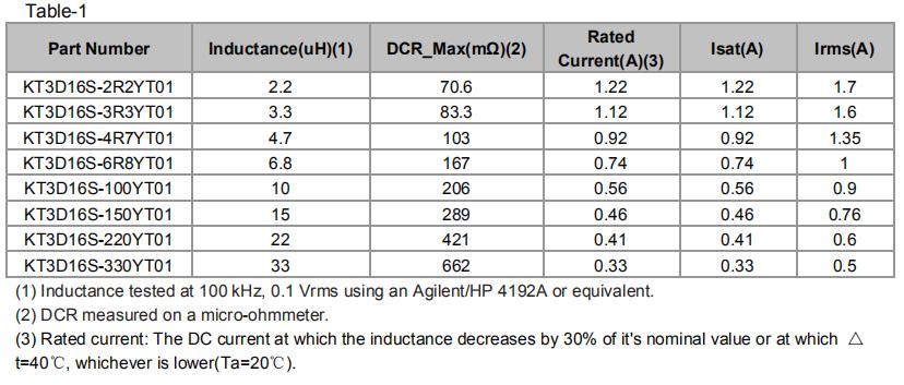
Power Inductor Parameters Inductor performance can be described by a relatively few parameters. Table 1 shows a typical data sheet excerpt for a surface mount power inductor intended for dc-dc converters.
To use the ratings properly, one must understand how they were derived. Since it is not practical for a data sheet to show performance for all possible sets of operating conditions, it is important to have some understanding of how the ratings would change with different operating conditions.
Inductance (L)
Inductance is the main parameter that provides the desired circuit function and is the first parameter to be calculated in most design procedures. Inductance is calculated to provide a certain minimum amount of energy storage (or volt-microsecond capacity) and to reduce output current ripple. Using less than the calculated inductance causes increased ac ripple on the dc output. Using much greater or much less inductance may force the converter to change between continuous and discontinuous modes of operation.
Tolerance of Inductance Fortunately most dc-dc converter applications do not require extremely tight tolerance inductors to achieve these goals. It is, as with most components, cost effective to choose standard tolerance parts and most converter requirements allow this. The inductor in Table 1 is shown specified at ±30% which is suitable for most converter applications.
Test Conditions
(1) Voltage level The inductance value rating should note the applied frequency and test voltage. Most catalog inductance ratings are based on “small” sinusoidal voltages. This is the easiest and most repeatable method for the inductor makers, and suitably indicates the inductance for most applications. Test voltage level 0.1V is popularly used to measure the inductance value.
( 2 ) Test Frequency. Most power inductors do not vary dramatically between 20 kHz and 500 kHz so a rating based on 100 kHz is quite often used and suitable. It must be remembered that inductance eventually decreases as frequency increases. This can be due to the frequency roll off characteristic of the core material used or it may be due to the SRF(Self- Resonance Frequency) of the winding inductance resonating with its stray capacitance. As most converters operate in the 50 kHz to 500 kHz range, 100 kHz has been a suitable standard test frequency. As switching frequencies increase to 500 kHz, 1 MHz, and above, it will be more important to consider ratings based on the actual application frequency.
DC Resistance (DCR) DCR is simply a measure of the wire used in the inductor. It is based strictly on the wire diameter and length. Normally this is specified as a “max” in the datasheets, but can also be specified as a nominal with a tolerance. This second method can be a little more instructive by giving a better indication of the nominal or expected resistance, but also may unnecessarily tighten the specification as almost always no harm is done by a part having too little resistance. DCR varies with temperature in the same manner as the resistivity of the winding copper.It is important that the DCR rating makes note of the ambient test temperature. The temperature coefficient of resistance for copper is approximately +0.43% per degree C. So the part shown rated at 10mΩ max would have to have a corresponding rating of 13 mΩ max at 85°C, only a 3mΩ difference in this case, but a total change of about 25%( 0.43%X60=25.8% ). R=R0(1+αt) R --- resistance at temperature t℃ R0 ---resistance at temperature 0℃; α --- resistance temperature coefficient in unit 1/℃, α=0.0043/℃, k=1/α, approximately equal to 234.5 within the range of 50~100℃
AC Resistance This is a parameter that is not commonly shown on inductor data sheets and is not typically a concern unless either the operating frequency or the ac component of the current is large with respect to the dc component.
The resistance of most inductor windings increases with operating frequency due to skin effect. If the ac or ripple current is relatively small compared to the average or dc current then the DCR gives a good measure of the resistive loss to be expected. The skin effect varies with wire diameter and frequency.
Irms(Temperature Rise Current) The second major effect of current is component self-heating. The RMS current is used to give a measure of how much average current can continuously flow through the part while producing less than some specified temperature rise. In this case the data sheets almost always provide a rating based on application of dc or low frequency ac current, so this does not include heating that may occur due to skin effect as mentioned earlier or other high frequency effects. The current rating may be shown for a single temperature rise point as in the example, or helpful graphs of temperature rise versus current or factors are provided that can be used to calculate temperature rise for any current.
The Irms rating should include the ambient temperature at which it was measured. Normally an inductor specification includes an operating temperature range. This is the range of ambient temperature environment within which the inductor is expected to be used. Temperature rise due to self heating may cause the inductor to be at a temperature higher than the rated range. This is normally acceptable provided the insulation ratings are not exceeded.
As with other parameters it is important to know the inductor temperature rise so this can be traded off with other parameters when making design choices. If lower temperature rise is desired, a larger size component is most likely the answer. Higher self-heating decreases the efficiency of the component.
Isat(Saturation Current) Isat is the amount of continuous DC bias current flowing through a magnetic components which causes its inductance to drop by a specified amount from the initial zero DC bias inductance value due to magnetic core saturation.
This saturation rating current Isat is defined as the current at which the inductance usually decreases by 30% from its initial value at 20℃ ambient in energy storage applications. Saturation Current Isat is also called DC Superposition Current.
Saturation current depends on the core material’s property and temperature,The inductance will decrease sharply when the loading current is over the rating, cause to produce bigger ripple current to destroy the inductor.
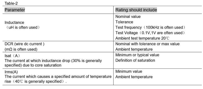
Summary It can be seen that inductors for dc-dc converters can be described by a small number of parameters. However each rating may be thought of as a “snapshot” based on one set of operating conditions which may need to be augmented to completely describe expected performance in application conditions. Table 2 only summarizes the visible ratings that should appear in a power inductor data sheet.