Self Resonance of Inductors
Ideal inductors would have zero resistance and zero capacitance. But, real inductors have “parasitic” resistance and capacitance.
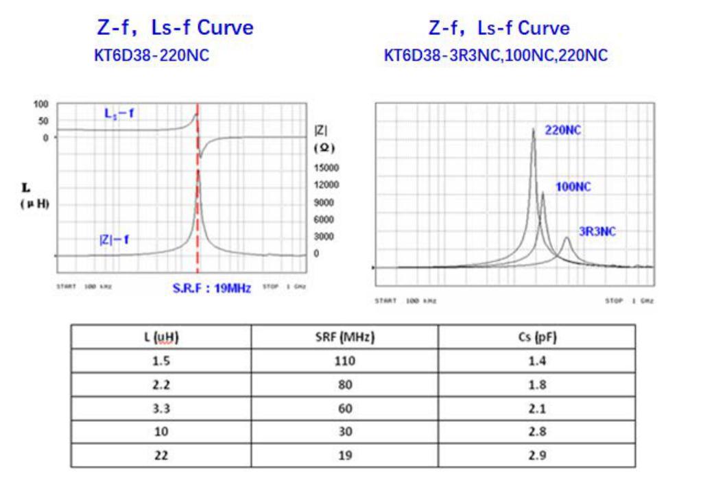
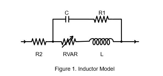
The first self resonant frequency of an inductor is the lowest frequency at which an inductor resonates with its self-capacitance. The first resonance can be modeled by a parallel combination of inductance and capacitance shown in Figure 1. Resistor “R1” limits impedance near the resonant frequency
At the SRF of an inductor, all of the following conditions are met: • The input impedance is at its peak. • The phase angle of the input impedance is zero, crossing from positive (inductive) to negative (capacitive). • Since the phase angle is zero, the Q is zero. • The effective inductance is zero, since the negative capacitive reactance (Xc = 1 / jωC) just cancels the positive inductive reactance (XL = jωL). A measurement of any of these conditions can be used to determine the SRF of an inductor. How to Measures Inductor SRF An Agilent/ HP Vector Network Analyzer and/or Impedance Analyzer and the appropriate test fixture shall be used to measure the SRF of all our chip inductors and power inductors. The SRF is determined to be the frequency at which the insertion (S21) phase changes from negative through zero to positive.
Because SRF measurements are so sensitive to fixture effects, we specify the SRF for our low inductance RF chip inductors as a “minimum” value, approximately 15% to 20% below the actual average measurement of a representative sample. Since fixture effects become negligible for higher inductance values, SRF for power inductors is usually specified as “typical.”
How Capacitance Affects SRF
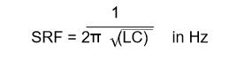
Historically, inductor capacitance is called “inter-winding capacitance” based on the assumption that it is the result of charge separation between insulated coil windings. However, if the inductor is measured over a conducting ground plane, capacitance between the coil and the ground plane is also part of the measurement. The distance of the coil from the measurement ground plane and the effective dielectric constant of the measurement substrate affects the capacitance to ground. This partially explains how the test fixture affects the SRF measurement. The following equation shows how the SRF is related to inductance and capacitance in an LC circuit.
Where: L is the inductance in Henries C is the capacitance in Farads From this equation, it is clear that increasing inductance or capacitance lowers the measured SRF. Reducing inductance or capacitance raises the SRF
Fixture Effects on SRF Measurements A fixture is required to connect an inductor to the terminals of a test instrument. After calibration and fixture compensation are performed, it is assumed that all fixture effects have been deembedded (removed) from the measurement. Fixture compensation uses open and short standards, but it cannot predict the interaction of a specific inductor with the test fixture. Therefore, some residual capacitance between the measured inductor and the fixture may exist after calibration and fixture compensation. The result is that SRF measurements of the same inductor can change with each different combination of instrument and fixture. The specific instrument and fixture shall be stated to be used to measure the SRF of its inductors. To illustrate the effect of residual fixture capacitance on SRF, The following Figure-1 plots the effective series inductance of a 100 nH chip inductor . Curve-1 shows the effect of an additional 0.01 pF of capacitance to ground at the input terminal. The term “effective inductance” is used, because the low-frequency inductance is the same (100 nH) for both models, but the inductance near the SRF is affected by capacitance between the inductor and the fixture.

The effect of residual fixture capacitance is more pronounced on lower value inductors. The effect of residual fixture capacitance on larger power inductors is often negligible. Several important conclusions can be made from the above illustration: • A slight difference in fixture design and calibration can have a large effect on the measured SRF. • In the region of the measured SRF, a small difference in fixture design and calibration can mean the difference between reading a large positive inductance or a large negative capacitance. • If the parasitic capacitance (and inductance) of the circuit board to which an inductor is attached is different from the test fixture, the SRF measurement of the board- mounted inductor will be different. • Since SRF measurements are fixture/substrate-dependent, a “typical” SRF cannot be defined when the fixture effect is significant.
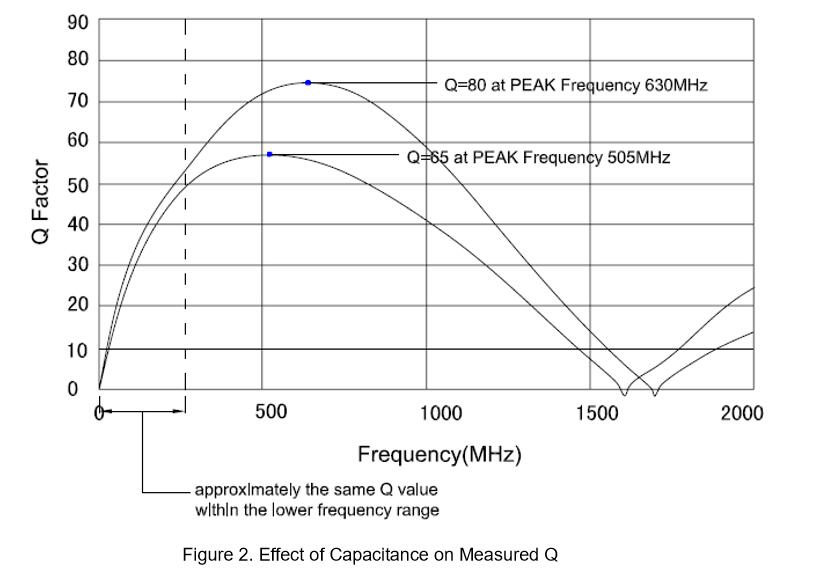
How Small Differences in Capacitance Affect Q
Figure 2 illustrates the effect of residual fixture capacitance on Q values. The values represent the Q for the original inductor model plotted in Figure 1 compared to the Q of the same inductor with an additional 0.01 pF of capacitance to ground at the input terminal. At lower frequencies, the residual fixture capacitance has little effect on the Q value. At higher frequencies, the effect on Q becomes significant. In this example, the small residual capacitance to ground causes the peak Q frequency to left shift by 125 MHz and to decrease in magnitude by 20% of the original value.
Simulating Substrate-Dependent SRF Remeasuring the SRF of inductors for each new application circuit board is clearly not convenient or timely for circuit designers. The true SRF of any inductor always depends on the specific characteristics of the circuit board to which it is mounted. In other words, the SRF is substrate-dependent.
By simulating the model over a specific circuit board substrate, you can determine the SRF of an inductor for your application. The circuit board substrate dielectric constant and thickness, and the size and layout of the conductor traces in the vicinity of the inductor determine the SRF of the inductor.
By applying the circuit board characteristics and tolerances to the simulation, circuit designers can see the effects they have on the SRF and all other electrical characteristics, such as inductance, Q, input impedance, phase, insertion loss and return loss. This knowledge gives the designer a practical basis to apply when comparing inductors, and ultimately can answer the question of whether an inductor is appropriate for the application.