The rapid growth of smart phones, web, video and audio applications has increased the demand for high-speed systems. As more and more users need high-speed data, operators need higher capacity base station network with higher modulation and bandwidth support functions. The base station network supporting microwave backhaul in the frequency range of 6 to 42ghz can send data from many users to the central backbone network. The data from these networks is not only one order of magnitude higher than that from a user or a user segment, but also requires higher modulation level support functions.
Such a high modulation scheme can bring more challenges to the transmitter and receiver. As the number of symbols increases, the system needs higher SNR or lower noise. Because the ratio of peak to average of this kind of signal is relatively larger, better linearity is needed.
When phase noise, system thermal noise and clock jitter exist, the measurement of transceiver quality performance is mainly expressed in the form of error vector magnitude (EVM). In the use cases of direct conversion modulators and demodulators, there are other forms of impairment, such as local oscillator (LO) leakage in the transmitter, DC offset in the receiver, IQ amplitude and phase imbalance. EVM can measure the difference between the measured symbol position and the ideal symbol position of digital modulation waveform. EVM is related to system SNR. An ideal system with zero noise, nonlinear distortion, frequency error and IQ imbalance will have excellent SNR (theoretically infinite) and zero EVM. The reason of EVM reduction is the large error distance between reference symbol position and measurement symbol position, which is caused by system noise and distortion.
Trf2443 is a full duplex if transceiver, which supports wireless microwave backhaul, point-to-point microwave and broadband wireless applications. It is integrated with the transmit (TX) and receive (Rx) chains. TX integrates a quadrature modulator, high linearity DVGA and synthesizer. The RX chain integrates IQ demodulator, analog VGA, digital VGA and synthesizer. In addition, trf2443 can also support cross polarization interference cancellation (XPIC) through a separate integrated IQ demodulator receiving chain.
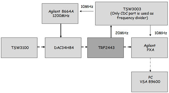
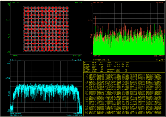
Figure 1 below is a block diagram of the measurement setup used to evaluate the trf2443 transmitter. 20MHz on-board crystal oscillator is used to lock all instruments. CDCM7005 on tsw3003 is used to divide 20MHz crystal oscillator reference into 10MHz. Figure 2 is a picture of the measurement setup. Figure 3 shows the EVM 1.1% of 56mhz 1024 QAM trf2443 transmission chain.
Fig1: trf2443 transmitter evaluation setting block diagram
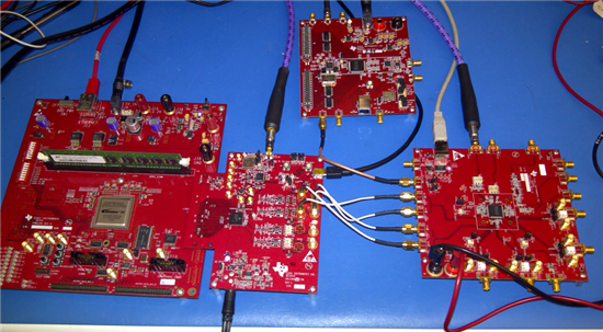
Fig 2: trf2443 transmitter setting diagram
Fig3: trf2443 transmit 56mhz 1024qam error vector amplitude
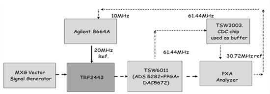
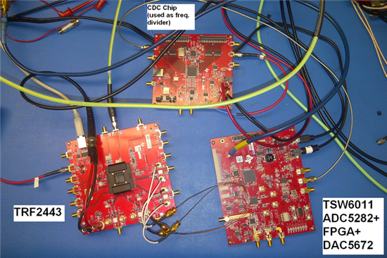
Figure 4 is the experimental setup block diagram of trf2443 receiver. Tsw6011 is a single channel reference design using ads5282 and dac34h84.
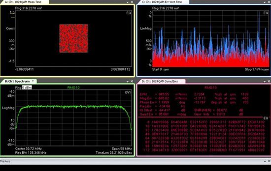
Figure 5 is the setup diagram, and Figure 6 is the 0.945% 56mhz 1024 QAM signal EVM of trf2443 + ads5282 + dac5672 cascade output.
Fig4: trf2443 receiver evaluation setup block diagram
Fig 5: trf2443 receiver setup diagram
Fig 6: trf2443 receives 56mhz 1024 QAM error vector amplitude
Higher modulation level will not only bring more system challenges, but also need better SNR. Please evaluate the performance of your system and let me know the results.